In diesem Thread: https://abbuc.de/forum/viewtopic.php?p=36044#p36044
habe ich eine Beschreibung und den Status des Projekts zum Zeitpunkt der Einreichung beim Abbuc HW 20025-Wettbewerb vorgestellt. Hier möchte ich euch über den Fortschritt und die Herausforderungen bei der Entwicklung der Benutzeroberfläche informieren. Da der Wettbewerb noch nicht abgeschlossen ist, kann ich nicht alle technischen Details verraten, denke aber, dass ich die Entwicklungsphasen und Möglichkeiten zur Fehlerbehebung aufzeigen kann. Ich werde auch versuchen, die im Gerät verwendeten Komponenten zu erläutern, damit sie später in anderen Projekten verwendet werden können.
Dieser Text wurde automatisch aus dem Englischen übersetzt – bitte verzeiht mir also etwaige Unklarheiten oder Rechtschreibfehler.
Mehr über TasmARI könnt ihr im oben verlinkten Beitrag lesen. Kurz gesagt: TassmARI ist ein einfaches Gerät, das über den SIO-Anschluss mit einem Atari verbunden wird und über WLAN mit IoT-Geräten über das MQTT-Protokoll kommunizieren kann. Dadurch kann der Atari als Controller für unser digitales Zuhause genutzt werden. Das Herzstück der TasmARI-Schnittstelle ist ein Modul, das auf dem ESP32-Mikrocomputer läuft – einem sehr beliebten Mikrocomputer mit umfangreichen Anwendungen in den meisten IoT-Geräten. Ich habe mich für ESP32 entschieden, weil mehrere sehr fortschrittliche Betriebssysteme für diesen Mikrocomputer entwickelt wurden, darunter Tasmota. Aus der Kombination der Wörter Tasmota und Atari entstand TasmARI. :-)
Blockschaltbild
- TasmARI Block Diagram
- TasmARI_block.png (12.26 MiB) 10864 mal betrachtet
PCB-Visualisierung erstellt in KiCAD:
- Visualization FRONT
- Tasmari_1.0RC1-front.png (159.08 KiB) 10864 mal betrachtet
- Visualization BACK
- TasmARIv1.0RC1-back.png (103.27 KiB) 10864 mal betrachtet
- PCB 1.0R1
- signal-2025-08-07-153855_004.jpeg (874.79 KiB) 10864 mal betrachtet
- PCB 1.0R1 - equipped
- signal-2025-08-07-153855_002.jpeg (873.51 KiB) 10864 mal betrachtet
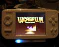
- First Display Test
- signal-2025-08-07-153855_005.jpeg (988.71 KiB) 10864 mal betrachtet
Br,
pancio